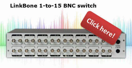
XLR switcher based on relay switches is one of the best solutions for applications requiring low audio distortion. The relay switches with gold plated contacts ensure high reliability. The bistable relays also sustain its state during device power off state. The low insertion loss of mechanical relay switches makes the LinkBone 1-to-15 switch perfect for of low level microphone signals.
This article is related with the following products:
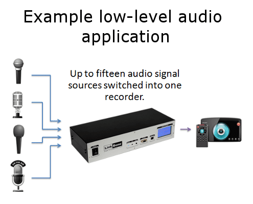
The following picture shows an connection example with up to 15 signal sources and one receiver using XLR switcher.
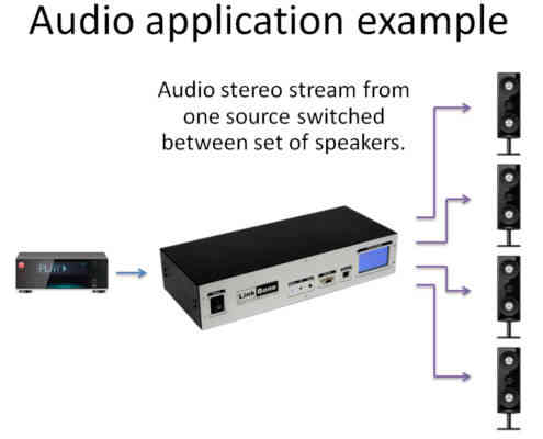
The LinkBone XLR switcher routes signal bidirectionally. This means that the device can be used also for signal distribution. E.g from one source to multiple signal receivers as proposed in the following connection example:
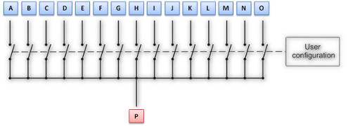
XLR Switcher connection diagram
The following diagram shows the connection diagram of internal XLR switcher network. There are fifteen ports from A to O which can be connected to common node P. The user can configure state of each individual port via touch screen on device front panel or remotely.
XLR Switcher remote control via Web interface
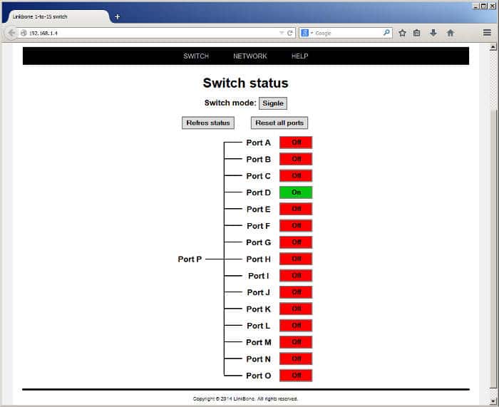
All LinkBone switches have an 10/100 Ethernet interface. The XLR switcher can be controlled remotely via Web interface shown on the following figure:
Additionally the device can be used for test automation by using an command line telnet interface. The list of commands supported by XLR switcher:
off <port> – turns off the specified port
on <port> – turns on the specified port
reset – disconnects all ports
mode <mode> – sets the mode of the switches
<mode>parameter can have two values:
single – only one port can be connected at the time. The device operates as a multiplexer.
multi – multiple connections are allowed to common port P.
https://linkbone.com/wp-content/uploads/2013/04/linkbone.png00LinkBonehttps://linkbone.com/wp-content/uploads/2013/04/linkbone.pngLinkBone2015-06-15 19:51:072015-06-15 20:48:23XLR switcher for professional audio with remote control
All new Rigol oscilloscopes have support for National Instruments Visa programming and control standard. This can be a great tool when implementing measurement or test automation functions. This tutorial explains how to use National Instruments Visa to control Rigol oscilloscopes via USB. This text focuses on Rigol DS1074Z oscilloscope model but is also applicable for DS2000 and DS4000 models. The included C example source code demonstrates how to setup connection to the Rigol oscilloscope in 5 steps.
Rigol oscilloscope remote control with NI-Visa in 5 steps
Step 1: Download and install National Instruments Visa environment. The link to the NI-Visa page is included here:
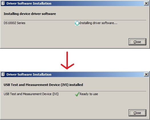
Step 2: After successful installation of the NI-Visa connect your Rigol DS1074Z oscilloscope to PC via USB. If needed install all necessary IVI drivers for your oscilloscope (if you don’t have them please visit Rigol DS1074Z website)
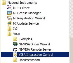
Step 3: To test the remote connection interface run the Visa Interactive Control tool from National Instruments program group.
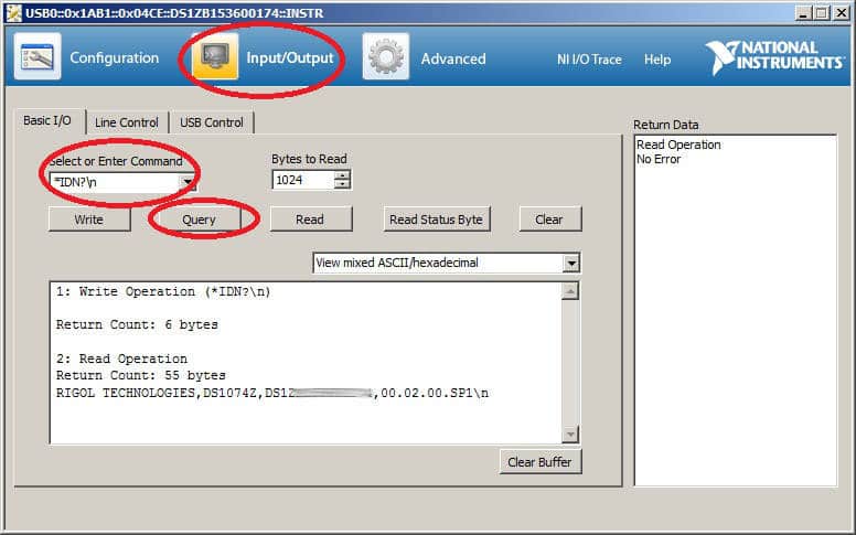
After running the Visa Interactive Control tool all recognized instruments should be visible in USB Instrument Resources drop down list.
Double clicking on the instrument identification string will display a window with instrument information and name. To test the communication command channel please click on “Input/Output” tab at the top of the window. Then type in command field “*IDN?\n” command and click on Query button. The text box will display the response from the oscilloscope. For more SCPI commands accepted by Rigol DS1000Z series oscilloscopes please refer to DS1000Z Programming Guide.
Step 4: If not done already install your favorite C/C++ environment. This can be for example:
Create a project file and add visa32.lib file from C:\Program Files (x86)\IVI Foundation\VISA\WinNT\lib folder. In lib\bc folder you can find visa32.lib file for Borland compilers. In lib\msc folder you can find visa32.lib for Microsoft environments.
Step 5: To start using NI Visa functions in your project you need to include the “visa.h” header file. The file can be find in header file directory at C:\Program Files (x86)\IVI Foundation\VISA\WinNT\include . You can also copy the file visa.h and visatype.h into your project include directory and add the following line of code to your main program:
#include "visa.h";
Now in your main() function add the following code to detect available instrument resources:
static ViSession defaultRM;
static ViSession rigolOsc=NULL;
static ViUInt32 numInstrs;
static ViFindList findList;
static ViUInt32 readCount;
static ViUInt32 writeCount;
static ViStatus status;


static char strInput[512],strOutput[512];
static char instrResourceString[VI_FIND_BUFLEN];

//open resource manager
status = viOpenDefaultRM (&defaultRM);
if (status < VI_SUCCESS)
return 0; // cannot open resource manager

//find USB instruments resources
status = viFindRsrc (defaultRM, "USB?*INSTR", &findList, &numInstrs, instrResourceString);
if (status < VI_SUCCESS)
return 0; // error finding USB instruments resources

//open Visa session to first instrument resource
status = viOpen (defaultRM, instrResourceString, VI_NULL, VI_NULL, &rigolOsc);
if (status < VI_SUCCESS)
return 0; // error opening Visa session to first instrument resource

//send *IDN? command to the device
strcpy (strInput,"*IDN?\n");
status = viWrite (rigolOsc, (ViBuf)strInput,512 , &writeCount);

status = viRead (rigolOsc, (ViBuf)strOutput,512, &readCount);
if (status < VI_SUCCESS)
{
// cannot read from the device
viClose (rigolOsc);
return 0;
}

//please include here your Rigol ID returned by Visa Interactive Control tool
char RigolOscID[] ={"RIGOL TECHNOLOGIES,DS1074Z,xxxxxx\n"};

if(!strcmp(RigolOscID,strOutput)==0)
{
viClose (rigolOsc); // error this is not our DS1074 oscilloscope
return 0;
}
Whats next?
Please refer to DS1000Z Programming Guide for oscilloscope SCPI commands for remote control. One interesting feature in test automation applications is pass/fail test. It allows to test the signal waveform by applying specified signal mask. If the signal fits into the specified mask region the test is reported as passed. In case of signal mask hit test is reported as failed. This allows to test various analog and digital signal waveforms.
To enable the pass/fail test remotly in your oscilloscope include this function in your project:
And then after NI-Visa initialization function include the following set of command:
status = viCmd(rigolOsc,":MASK:ENABle 1");
status = viCmd(rigolOsc,":MASK:MDISplay ON");
status = viCmd(rigolOsc,":MASK:SOOutput OFF");
status = viCmd(rigolOsc,":MASK:SOURce CHAN1");
https://linkbone.com/wp-content/uploads/2013/04/linkbone.png00LinkBonehttps://linkbone.com/wp-content/uploads/2013/04/linkbone.pngLinkBone2014-08-16 15:54:402021-12-15 14:17:38Rigol oscilloscope remote control with NI-Visa (SCPI commands)
Summary: this article explains how to use LinkBone BNC switches in automated prototype hardware testing in development phase and production lines. The presented test automation environment is using the bed of nails tester fixture. The source code for remote instrument control and test script is included.
This article is related with the following products:
During the prototype development process engineers have to focus on the right quality of a product. This involves high number of hardware tests in different temperature profiles and often involving measurements done by hand. This process takes long time and involves human factor leading to errors. In case of production line testing, manual measurements take too much time. More efficient and reliable way of executing tests is by automated hardware test setup. The example of simple and low cost test environment is bed of nails with a signal multiplexer and oscilloscope.
Hardware testing with bed of nails tester fixture
Figure 1: Simple PCB used as bed of nails on the hardware prototype test place.
The figure 1 shows an bed of nails tester fixture made using a simple PCB with test probes. When placing the bed of nails tester on the tested prototype, nails are contacting the PCB test points. When having high number of test points it can be difficult to find an measurement equipment having sufficient number of inputs. One option is to use the LinkBone BNC switch which can be used as a signal multiplexer/demultiplexer. In this approach only an oscilloscope with remote control interface and pass/fail automated test is needed. The bed of nails test pins are connected to the oscilloscope using a BNC switch remotely controlled via a automated test script.
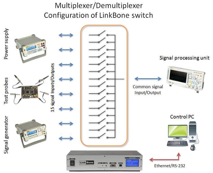
The figure 2 shows the proposed automated hardware test setup. The BNC switch is routing signals from prototype test probes(or bed of nails tester), power supply and system clock from signal generator. The BNC switch and oscilloscope are controlled remotely via a test PC executing script or program. The remote control is done via 10/100 Ethrernet or RS-232 interfaces.
Figure 2: Automated hardware testing setup with LinkBone BNC switch.
The following set of commands switches the oscilloscope input between A,B,C,D ports of LinkBone BNC switch. The device port connections are based on electromechanical switches that is why analog or digital signal can be routed bidirectionally. This allows to use the switch not only for probing the test points but also for signal distribution.
reset
mode single
on A
on B
on C
on D
The BNC switch from LinkBone can be controlled remotely via a set of text command. The following two articles explain how to control the switch from C++ or Python program level:
Oscilloscope with Pass/fail test mask in hardware testing
Figure 3: Oscilloscope pass/fail test for prototype hardware testing.
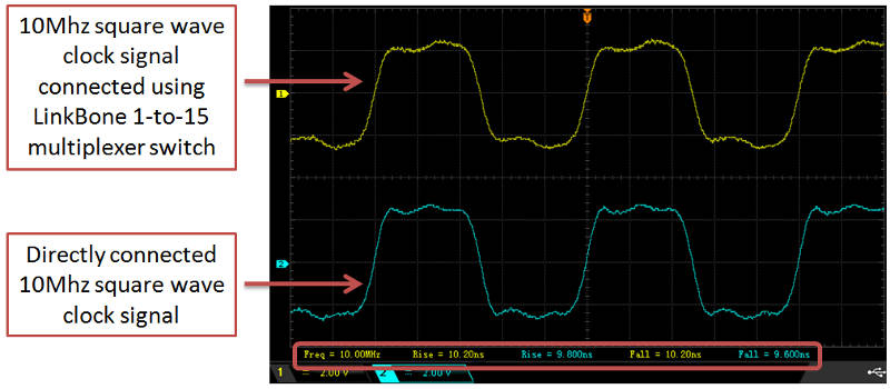
The figure 3 shows the oscilloscope used in pass/fail signal test. The yellow plot represents the measured signal. The blue mask specifies the expected signal plot. When measured signal plot hits the signal mask the oscilloscope reports test as fail. Otherwise the test is reported as passed. User can specify the signal mask margin in case of high signal variation or jitter.
Figure 4: 10Mhz test signal connected directly to the oscilloscope and routed via a BNC switch.
The yellow signal plot on figure 4 represents 10Mhz signal routed via the LinkBone BNC switch to the oscilloscope. The blue plot shows the signal connected directly. In both cases the signal rise and fall times are 10ns. This illustrates the low signal distortion added by the BNC switch during hardware testing process.
https://linkbone.com/wp-content/uploads/2013/04/linkbone.png00LinkBonehttps://linkbone.com/wp-content/uploads/2013/04/linkbone.pngLinkBone2014-08-06 15:53:272024-01-26 22:04:50Automated hardware testing in production lines and R&D
The XLR switch and BNC switch from LinkBone can be remotely controlled via a Ethernet or RS-232 interfaces from Python environment. This article explains how to prepare an Python environment for remote control of XLR switches. The complete python module implementations and code examples are included.
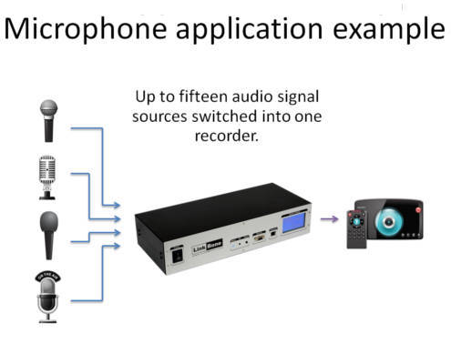
The example application using XLR switch as a microphone multiplexer is shown on the following drawing:
The LinkBone XLR switch is routing signals from microphone to the audio recorder. As all signal lines are bidirectional the LinkBone XLR switch can be also used in audio distribution to a set of a speakers from single audio source. The device can be controlled manually via touch screen or IR remote control. The second option is remote control via 10/100Ethernet or RS-232 interfaces. The Python environment can be used for control of the XLR switches. All LinkBone devices also include visual web interface(http) shown on the following picture:
Preparing Python environment for XLR switch
Before starting, make sure that you have already installed Python 3 on your machine. If not, you can easily download it from official page. You need also Python Serial Port Extension (pyserial), which encapsulates the access for the serial port. You can find this module here. Finally, you can download our Python modules from our website:
Module RS232linkbone.py for remote control via RS-232 can be found here
Module TELNETlinkbone.py for remote control via Telnet can be found here
Please note, that these libraries are intended to use in Python 3.0
XLR switch with remote control via RS-232 in Python
The LinkBone XLR switch can be controlled via serial RS-232 from Python program level. The following paragraph shortly explains how to setup a serial port and send text commands to the device using Python scripts.
First, the RS232linkbone module has to be imported:
import RS232linkbone
Using rs232 class from RS232linkbone module, serial connection to LinkBone switch can be established, for instance:
serial = RS232linkbone.rs232("COM12", 9600, "N", 1, False)
Serial connection to LinkBone has been established!
Serial<id=0x364e270, open=True>(port='COM12', baudrate=9600, bytesize=8, parity='N', stopbits=1, timeout=1, xonxoff=False, rtscts=False, dsrdtr=False)
Class rs232(port, baudrate, parity, stopbits, rtscts) takes the following arguments:
rtscts – hardware control flow, True (data is transmitted using RTS / CTS control flow according to the RS-232 standard) or False (data is transmitted without control flow mechanism)
After setting the serial port, test commands can be send to the switch by using sendCommand(command) method.
# send control commands to LinkBone XLR switch with remote control
serial.sendCommand("mode single")
Done.
serial.sendCommand("on a")
Done.
A good practice is to close serial port, when you finish your work with LinkBone switch. The following code can be used for closing serial port connection.
serial.close()
XLR switch with remote control via Telnet in Python
The LinkBone XLR switch can be also controlled via Telnet from Python program level. The following paragraph shortly explains how to setup a Telnet connection and send text commands to the device using Python scripts.
First, the TELNETlinkbone module has to be imported:
import TELNETlinkbone
Using telnet class from TELNETlinkbone module, telnet connection to LinkBone switch can be established, for instance:
telnet = TELNETlinkbone.telnet("169.254.89.200")
Telnet connection to LinkBone has been established!
Class telnet(ip) takes the following argument:
ip – ip address of LinkBone switch
After setting the telnet connection, test commands can be send to the switch by using sendCommand(command) method.
# send control commands to LinkBone XLR switch with remote control
telnet.sendCommand("reset")
Done.
telnet.sendCommand("mode multi")
Done.
telnet.sendCommand("on a b c d")
Done.
After finishing work with LinkBone switch, telnet connection can be closed. The following code can be used for closing telnet connection.
Source code of module RS232linkbone.py for remote control via RS-232 can be found here, whereas module TELNETlinkbone.py for remote control via Telnet can be found here.
https://linkbone.com/wp-content/uploads/2013/04/linkbone.png00Marcinhttps://linkbone.com/wp-content/uploads/2013/04/linkbone.pngMarcin2014-07-17 19:06:582014-10-02 21:43:34XLR switch remote control via RS-232 and Telnet from Python
XLR switch and BNC switch with remote control via RS-232
Module can be used in Python 3.0.
//****************************************************//
//        Module: RS232linkbone.py                    //
//        Author: Marcin Debski                       //
//        XLR Switch and BNC Switch module for remote //
//        control via RS-232                          //
//        www.linkbone.com                            //
//****************************************************//
'''

import time
import serial

class rs232:
def __init__(self, port, baudrate, parity, stopbits, rtscts):
try:
ser = serial.Serial(
port=port,
baudrate=baudrate,
parity=parity,
stopbits=stopbits,
bytesize=serial.EIGHTBITS,
timeout=1,
rtscts=rtscts
)
print("Serial connection to LinkBone has been established!")
self.ser = ser
print(ser)
except:
print("Cannot connect via serial to LinkBone!")

# close serial connection
def close(self):
return self.ser.close()

# check if serial connection is already open
def isOpen(self):
return self.ser.isOpen()

# print information about status of the XLR switch and BNC switch
def getStatus(self):
self.ser.write(b'status\r')
time.sleep(1)
while 1:
status = self.ser.readline()
if status:
print(status.decode())
else:
break

# print list of available commands
def getHelp(self):
self.ser.write(b'help\r')
time.sleep(1)
while 1:
status = self.ser.readline()
if status:
print(status.decode())
else:
break

# print information about XLR switch and BNC switch device
def getInfo(self):
self.ser.write(b'info\r')
time.sleep(1)
while 1:
status = self.ser.readline()
if status:
print(status.decode())
else:
break

# send text command to LinkBone XLR switch and BNC Switch
def sendCommand(self, command):
self.ser.write(b''+str(command).encode()+'\r'.encode())
time.sleep(1)
while 1:
status = self.ser.readline()
if status:
print(status.decode())
else:
break
https://linkbone.com/wp-content/uploads/2013/04/linkbone.png00Marcinhttps://linkbone.com/wp-content/uploads/2013/04/linkbone.pngMarcin2014-07-17 18:29:592021-12-15 14:22:49XLR switch and BNC switch Python module for remote control via serial RS-232
XLR switch or BNC switch with remote control via Ethernet (Telnet)
Python module for remote control via Telnet
Module can be used in Python 3.0.
//****************************************************//
//        Module: TELNETlinkbone.py                   //
//        Author: Marcin Debski                       //
//        XLR Switch or BNC Switch module for remote  //
//        control via Telnet                          //
//        www.linkbone.com                            //
//****************************************************//
'''

import time
import threading
import telnetlib

class telnet:
def __init__(self, ip):
self.ip = ip
try:
tn = telnetlib.Telnet(ip)
print("Telnet connection to LinkBone has been established!")
self.tn = tn
self.thread = threading.Timer(60, self.pingSwitch)
self.run = 1
self.thread.start()
tn.read_until(b'Hello. Please enter your command:')
except:
print("Cannot connect via telnet to LinkBone!")

# keep telnet connection alive to XLR switch or BNC switch
def pingSwitch(self):
try:
while self.run:
self.tn.write(b'ping\n')
self.tn.read_until(b'Pong.')
time.sleep(60)
except:
pass

# print information about status of the XLR switch or BNC switch
def getStatus(self):
self.tn.write(b'status\r')
time.sleep(1)
while 1:
status = self.tn.read_very_eager()
if status:
print(status.decode())
else:
break

# print list of available commands
def getHelp(self):
self.tn.write(b'help\r')
time.sleep(1)
while 1:
status = self.tn.read_very_eager()
if status:
print(status.decode())
else:
break

# print information about XLR switch or BNC switch device
def getInfo(self):
self.tn.write(b'info\r')
time.sleep(1)
while 1:
status = self.tn.read_very_eager()
if status:
print(status.decode())
else:
break

# send text command to LinkBone XLR switch or BNC Switch
def sendCommand(self, command):
self.tn.write(b''+str(command).encode()+'\n'.encode())
time.sleep(1)
while 1:
data = self.tn.read_very_eager()
if data:
print(data.decode())
else:
break

# close telnet connection
def close(self):
self.run=0
self.tn.close()
https://linkbone.com/wp-content/uploads/2013/04/linkbone.png00Marcinhttps://linkbone.com/wp-content/uploads/2013/04/linkbone.pngMarcin2014-07-17 18:19:272021-12-15 14:08:45XLR switch or BNC switch Python module for remote control via Telnet
Summary: This article explains how LinkBone coaxial BNC switch can be used as a remote video multiplexer. Control of the device is possible via Web page from remote PC or via Infrared RC5 remote control. The RS-232 serial interface allows easy integration with other system components or standalone device operation. The LinkBone video multiplexer is a perfect choice for professional video processing applications and for industrial CCTV video multiplexing.
BNC switches from LinkBone can be used for video multiplexing in professional or industrial applications. Wide range of accepted voltage levels allow routing video and audio signals. Internal device signal lines have impedance matching to limit signal reflections. BNC input/output connectors are gold plated to limit resistance and ensure high contact reliability. Additionally internal signal lines have low capacitance to limit signal attenuation. The BNC video multiplexer can be mounted in 19-inch rack.
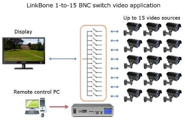
Video multiplexer example application
Figure 1: Multiplexing video signal from 15 cameras into one display.
Figure 1 shows example system with BNC switch used as a video multiplexer. Up to 15 signal sources can be connected to the device inputs. This can be a camera or any other signal source including audio. The selected input signals are multiplexed into one coaxial line. With Dual BNC switch version it is possible to multiplex up to 30 video sources into two coaxial signal lines. This allows to connect two video displays to fifteen CCTV cameras each. The control of the switch state is done via remote PC. The LinkBone BNC switches can be mounted in 19-inch rack to limit the installation space.
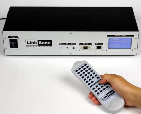
Figure 2: Infrared remote control of the LinkBone Video multiplexer BNC switch.
The video multiplexer can be controlled locally via an infrared remote control or a touch screen. The device accepts codes in RC5 standard. User can assign any specified port state configuration to the selected remote control button. The button assignment is done via a touch screen on the front panel.
Figure 3: Web interface for controlling switch state via 10/100Ethernet interface.
In applications where direct user access to the device is not possible a remote control over 10/100 Ethernet or RS-232 interfaces is possible. The telnet and http servers allow remote switch configuration. The video multiplexer switch can be also controlled via a web interface shown on figure 3. The http website displays a graphical representation of internal line switches. User can modify the port state by clicking on the status button.
Video multiplexer automatic switching using Arduino
The video multiplexer can be configured for automatic switching sequence execution. This can be done via a remote PC and a test script or program. More detailed instructions how to control the device via RS-232 text commands can be found in the following article:
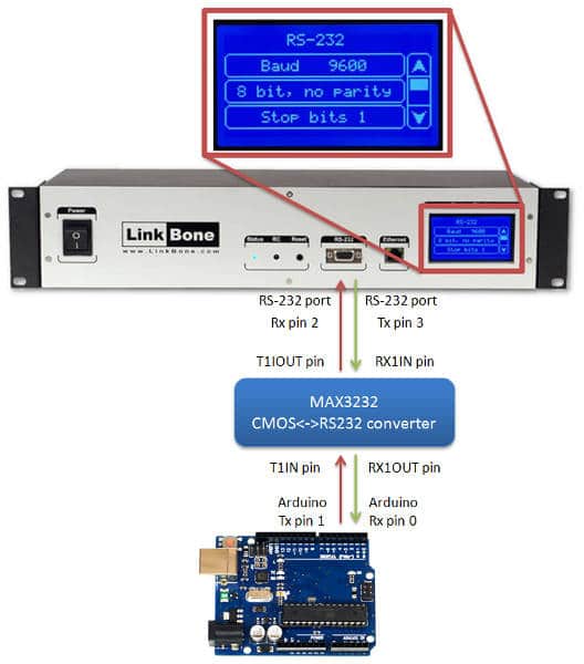
The Video multiplexer can be controlled without a test PC. For remote control an Arduino or any other system/evaluation board with RS-232 interface can be used. Figure 4 shows an example application with Arduino controlling the video multiplexer. Before establishing a serial RS-232 connection the LinkBone BNC switch has to be configured via a touch screen on the front panel. User can configure the baudrate, parity and stop bits.
Figure 4: Ardunio controlling the LinkBone video BNC multiplexer via RS-232 serial interface.
The following code is used to switch between A, B and C video inputs. The video input source is changed every 5 seconds. The setup() function initializes the Arduino serial port to 9800 baudrate with 1 stop and no parity bits. In the next step ‘reset’ and ‘mode’ commands are sent to the BNC switch.
The main loop() function sends text command sequence for switching between specified ports. The delay time between port switching can be adjusted by specifying different timing parameters in Sleep() function. The Serial.println() method sends text commands via serial RS-232 interface to the video multiplexer BNC switch.
//init the video multiplexer communication via serial RS-232
void setup()
{
//open serial port with 9600 baudrate, 1 stop bit, no parity
Serial.begin(9600);

//wait for the serial port to open
while (!Serial);

//reset/disable all inputs/outputs of the video multiplexer
Serial.println("reset");

//set the switching mode to multiplexer
Serial.println("mode single");
}

//main program loop
void loop()
{
//enable input A of video multiplexer BNC switch
Serial.println("on A");

//wait 5 seconds
delay(5000);

//enable input B of BNC multiplexer
Serial.println("on B");

//wait 5 seconds
delay(5000)

//enable input C of BNC multiplexer
Serial.println("on B");

//wait 5 seconds
delay(5000);
}
https://linkbone.com/wp-content/uploads/2013/04/linkbone.png00LinkBonehttps://linkbone.com/wp-content/uploads/2013/04/linkbone.pngLinkBone2014-07-10 18:02:552021-12-15 13:56:18Video multiplexer coaxial BNC switch with remote control via Ethernet, infrared and serial RS-232
The LinkBone 1-to-15 User guide v0.9 was released. Check out the Technical Resources->Specifications section. LinkBone
https://linkbone.com/wp-content/uploads/2013/04/linkbone.png00LinkBonehttps://linkbone.com/wp-content/uploads/2013/04/linkbone.pngLinkBone2014-07-07 09:21:052014-10-02 21:43:34LinkBone 1-to-15 User guide v0.9 was released
Summary: this article describes how to control LinkBone Coaxial switch with remote control via serial RS-232 interface. The complete code example in C++ with description is included.
This article is related with the following products:
The LinkBone Remote Coaxial BNC switch allows to connect different endpoints to the one common point. The device operation can be compared to the analog multiplexer forwarding signals from set of selected inputs/outputs into one signal line. Each link connection is bidirectional. Meaning that the device connected to the common port can be a signal source or receiver. The example of system with one common signal generator and several receivers is shown on figure 1. Read more
https://linkbone.com/wp-content/uploads/2013/04/linkbone.png00LinkBonehttps://linkbone.com/wp-content/uploads/2013/04/linkbone.pngLinkBone2014-07-02 22:55:482014-10-02 21:43:34Coaxial switch with remote serial RS-232 interface programming example
https://linkbone.com/wp-content/uploads/2013/04/linkbone.png00LinkBonehttps://linkbone.com/wp-content/uploads/2013/04/linkbone.pngLinkBone2014-07-01 14:51:552021-12-15 14:05:34Coaxial switch with remote control C++ example code