
Video multiplexer coaxial BNC switch with remote control via Ethernet, infrared and serial RS-232
Summary: This article explains how LinkBone coaxial BNC switch can be used as a remote video multiplexer. Control of the device is possible via Web page from remote PC or via Infrared RC5 remote control. The RS-232 serial interface allows easy integration with other system components or standalone device operation. The LinkBone video multiplexer is a perfect choice for professional video processing applications and for industrial CCTV video multiplexing.
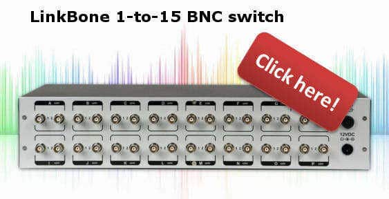
BNC switches from LinkBone can be used for video multiplexing in professional or industrial applications. Wide range of accepted voltage levels allow routing video and audio signals. Internal device signal lines have impedance matching to limit signal reflections. BNC input/output connectors are gold plated to limit resistance and ensure high contact reliability. Additionally internal signal lines have low capacitance to limit signal attenuation. The BNC video multiplexer can be mounted in 19-inch rack.
Video multiplexer example application
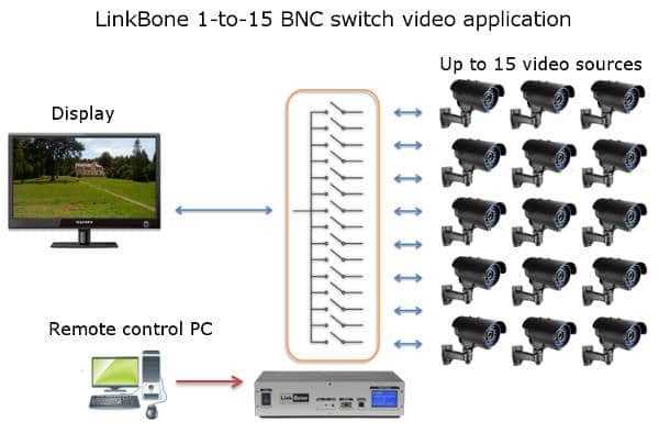
Figure 1 shows example system with BNC switch used as a video multiplexer. Up to 15 signal sources can be connected to the device inputs. This can be a camera or any other signal source including audio. The selected input signals are multiplexed into one coaxial line. With Dual BNC switch version it is possible to multiplex up to 30 video sources into two coaxial signal lines. This allows to connect two video displays to fifteen CCTV cameras each. The control of the switch state is done via remote PC. The LinkBone BNC switches can be mounted in 19-inch rack to limit the installation space.
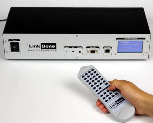
Figure 2: Infrared remote control of the LinkBone Video multiplexer BNC switch.
The video multiplexer can be controlled locally via an infrared remote control or a touch screen. The device accepts codes in RC5 standard. User can assign any specified port state configuration to the selected remote control button. The button assignment is done via a touch screen on the front panel.
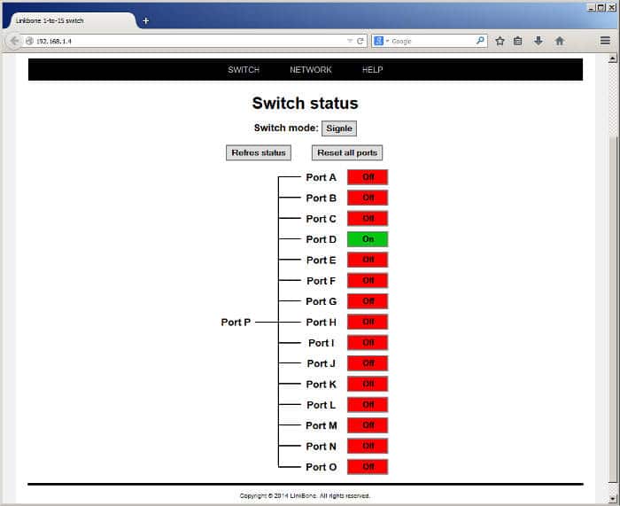
Figure 3: Web interface for controlling switch state via 10/100Ethernet interface.
In applications where direct user access to the device is not possible a remote control over 10/100 Ethernet or RS-232 interfaces is possible. The telnet and http servers allow remote switch configuration. The video multiplexer switch can be also controlled via a web interface shown on figure 3. The http website displays a graphical representation of internal line switches. User can modify the port state by clicking on the status button.
Video multiplexer automatic switching using Arduino
The video multiplexer can be configured for automatic switching sequence execution. This can be done via a remote PC and a test script or program. More detailed instructions how to control the device via RS-232 text commands can be found in the following article:
Coaxial switch with remote serial RS-232 interface programming example
The Video multiplexer can be controlled without a test PC. For remote control an Arduino or any other system/evaluation board with RS-232 interface can be used. Figure 4 shows an example application with Arduino controlling the video multiplexer. Before establishing a serial RS-232 connection the LinkBone BNC switch has to be configured via a touch screen on the front panel. User can configure the baudrate, parity and stop bits.
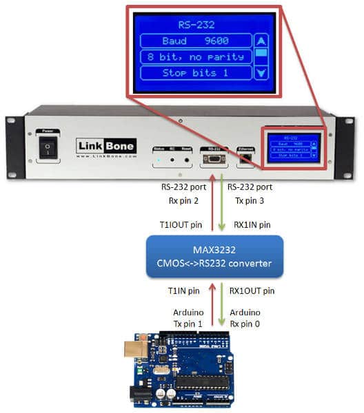
Figure 4: Ardunio controlling the LinkBone video BNC multiplexer via RS-232 serial interface.
The Ardunio project page can be found at: https://www.arduino.cc/
The following code is used to switch between A, B and C video inputs. The video input source is changed every 5 seconds. The setup() function initializes the Arduino serial port to 9800 baudrate with 1 stop and no parity bits. In the next step ‘reset’ and ‘mode’ commands are sent to the BNC switch.
The main loop() function sends text command sequence for switching between specified ports. The delay time between port switching can be adjusted by specifying different timing parameters in Sleep() function. The Serial.println() method sends text commands via serial RS-232 interface to the video multiplexer BNC switch.
//init the video multiplexer communication via serial RS-232
void setup()
{
//open serial port with 9600 baudrate, 1 stop bit, no parity
Serial.begin(9600);

//wait for the serial port to open
while (!Serial);

//reset/disable all inputs/outputs of the video multiplexer
Serial.println("reset");

//set the switching mode to multiplexer
Serial.println("mode single");
}

//main program loop
void loop()
{
//enable input A of video multiplexer BNC switch
Serial.println("on A");

//wait 5 seconds
delay(5000);

//enable input B of BNC multiplexer
Serial.println("on B");

//wait 5 seconds
delay(5000)

//enable input C of BNC multiplexer
Serial.println("on B");

//wait 5 seconds
delay(5000);
}