Automated hardware testing in production lines and R&D
Summary: this article explains how to use LinkBone BNC switches in automated prototype hardware testing in development phase and production lines. The presented test automation environment is using the bed of nails tester fixture. The source code for remote instrument control and test script is included.
This article is related with the following products:
During the prototype development process engineers have to focus on the right quality of a product. This involves high number of hardware tests in different temperature profiles and often involving measurements done by hand. This process takes long time and involves human factor leading to errors. In case of production line testing, manual measurements take too much time. More efficient and reliable way of executing tests is by automated hardware test setup. The example of simple and low cost test environment is bed of nails with a signal multiplexer and oscilloscope.
Hardware testing with bed of nails tester fixture

Figure 1: Simple PCB used as bed of nails on the hardware prototype test place.
The figure 1 shows an bed of nails tester fixture made using a simple PCB with test probes. When placing the bed of nails tester on the tested prototype, nails are contacting the PCB test points. When having high number of test points it can be difficult to find an measurement equipment having sufficient number of inputs. One option is to use the LinkBone BNC switch which can be used as a signal multiplexer/demultiplexer. In this approach only an oscilloscope with remote control interface and pass/fail automated test is needed. The bed of nails test pins are connected to the oscilloscope using a BNC switch remotely controlled via a automated test script.
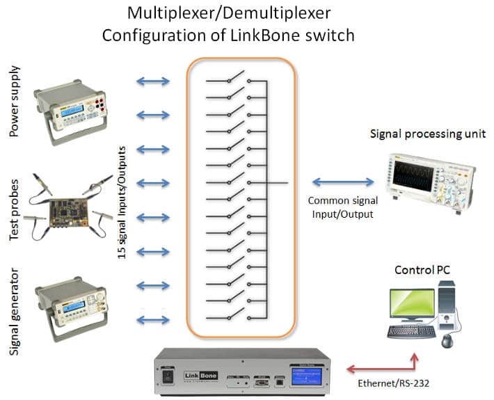
The figure 2 shows the proposed automated hardware test setup. The BNC switch is routing signals from prototype test probes(or bed of nails tester), power supply and system clock from signal generator. The BNC switch and oscilloscope are controlled remotely via a test PC executing script or program. The remote control is done via 10/100 Ethrernet or RS-232 interfaces.
Figure 2: Automated hardware testing setup with LinkBone BNC switch.
The following set of commands switches the oscilloscope input between A,B,C,D ports of LinkBone BNC switch. The device port connections are based on electromechanical switches that is why analog or digital signal can be routed bidirectionally. This allows to use the switch not only for probing the test points but also for signal distribution.
reset
mode single
on A
on B
on C
on D
The BNC switch from LinkBone can be controlled remotely via a set of text command. The following two articles explain how to control the switch from C++ or Python program level:
Control of BNC switches from C program via RS-232
Python programming example in automated hardware testing applications
Oscilloscope with Pass/fail test mask in hardware testing

Figure 3: Oscilloscope pass/fail test for prototype hardware testing.
The figure 3 shows the oscilloscope used in pass/fail signal test. The yellow plot represents the measured signal. The blue mask specifies the expected signal plot. When measured signal plot hits the signal mask the oscilloscope reports test as fail. Otherwise the test is reported as passed. User can specify the signal mask margin in case of high signal variation or jitter.
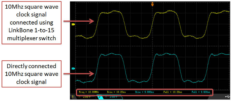
Figure 4: 10Mhz test signal connected directly to the oscilloscope and routed via a BNC switch.
The yellow signal plot on figure 4 represents 10Mhz signal routed via the LinkBone BNC switch to the oscilloscope. The blue plot shows the signal connected directly. In both cases the signal rise and fall times are 10ns. This illustrates the low signal distortion added by the BNC switch during hardware testing process.
References:


