Philips LivingColors / Hue lamp brightness increase with a LED strip
Philips LivingColors is a great lamp for creating colorful lightning effects depending on your mood. It is also a fun gadget to impress your friends. However the brightness of the lamp can be too low to fully light up the room. One solution is to get few Philips LivingColors lamps and place them around the room. The disadvantage of this option is the need to invest a few hundred bucks just for the lamp. The other more cost effective option which I wanted to describe here is increasing the lamp brightness by adding an extra LEDs.
The modification requires building a simple circuit on breadboard and soldering few wires to the lamp LED drivers.
Philips LivingColors brightness modification step by step
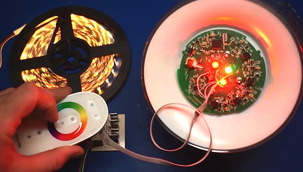
The final effect and instructions how to perform the modification can be seen in this video:
Please remove the power supply from the lamp first before doing any soldering!
Step 1: The lamp includes four high power LEDs with PWM drives. Adding the additional load to the drivers can result in circuit damage. That is why to drive safely the external LEDs we need four N-channel Mosfet transistors to increase driver current capacity. Additionally the transistors allow to connect voltage drivers directly to 12V LEDs strip. Assembly the transistor amplifier circuit according to the following schematic on the breadboard:
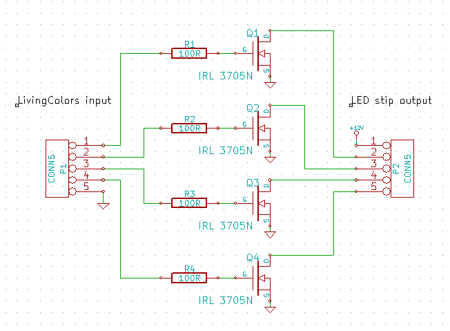
Philips LivingColors and LED strip connection schematic
I have used four IRL3705N transistors because of the gate threshold level compliant with 3.3V logic level. But you could use different transistor type with a gate threshold level below 3.3V. The 100R resistors values are not critical and can be replaced safely with resistor values within 50 to 200 Ohm range.
Step 2: Disassemble the lamp by removing the front plate to get the access to the PCB. Locate the suitable points for soldering the wires to the external transistor amplifier circuit. The LED colors with soldering points are shown on the following picture:
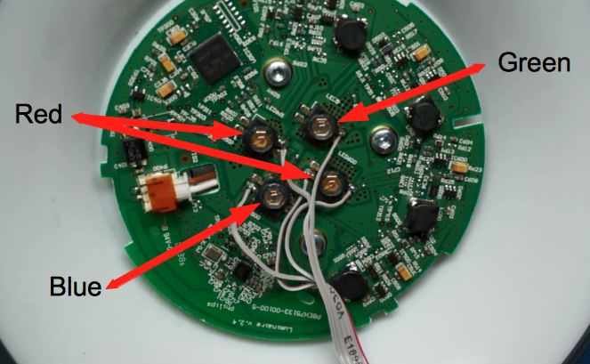
Step 3: Solder the wires to the RGB LED drivers on Philips LivingColors lamp PCB to the amplifier circuit prepared in step 1.
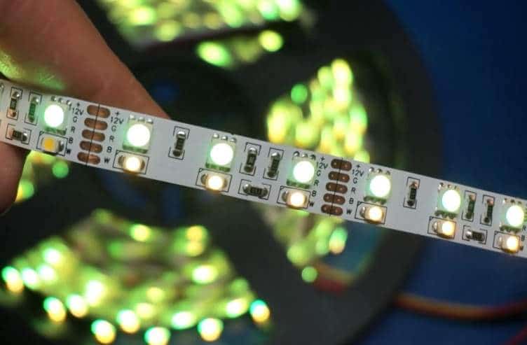
Step 4: Connect the transistor amplifier board to an LED strip. In the picture you can see an RGBW LED strip with 12V power supply. When selecting the LED strip please note that the common positive power supply should be connected to diode anode. This means that you have one +12V input and you drive all LEDs by shorting the RGBW lines to ground.
That’s all! I hope that enjoy the colorful lightning effects with your enhanced Philips LivingColors lamp.